Dayton Audio Ma1240a Multi-Zone 12 Channel Amplifier

SKU: PXP-300-815
  • Robust 60 WPC output at 4 ohms, 40 WPC output at 8 ohms
  • Independent and bus inputs enable unparalleled flexibility
  • Bridgeable channel outputs provide additional power when needed
  • Independent channel gain controls allow the output of each speaker to be perfectly matched
  • Multi-stage protection circuitry for reliability and easy troubleshooting of audio system
  • Temperature controlled cooling fans
  • ENERGY STAR and CE EuP directive compliant, consumes less than 1/2 a watt in standby
Unit Price
Quantity
Subtotal
US$ 721.88
US$ 819.99
US$ 721.88
US$ 819.99
US$ 717.551%
2
US$ 715.021%
3
Congratulations! You got a great price!
Add to cart Added
Checkout
Free shipping on orders over US$ 200
Buy more items from this warehouse and get free shipping!
Options
Brand
Model
MA1240a
Unit of Measure
Each
Barcode
844632081095
Dayton Audio MA1240a User Manual
Dayton Audio MA1240a Architectural & Engineering Specification Sheet
Dayton Audio MA1240a Set-Up Addendum Using In-Wall Volume Controls
Dayton Audio Manufacturer Warranty
Description
Dayton Audio MA1240a Multi-Zone 12 Channel AmplifierThe high-density solution to the challenges of multi-room audio

The Dayton Audio MA1240a features a Class-AB output circuit that delivers superior audiophile sound quality and stable performance. Each of your installation's zones can benefit from the MA1240a's clean audio reproduction and exceptional functionality.
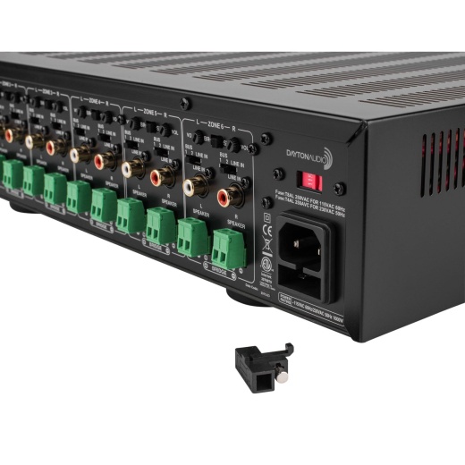
 The MA1240a can be stacked with other audio components and includes removable ears for mounting in standard audio racks (2RU).

Key Specs:
  • Channels: 12
  • Power Handling @ 8ohms (RMS): 40 Watts
  • Power Handling @ 8ohms (Bridged): 80 Watts
  • Frequency Response: 5Hz- 72kHz
  • Inputs: 2 Stereo Bus Inputs, 1 mono input per channel
  • Outputs: 2 Stereo Bus Outputs
We Got Your Back

We stand behind our products and our warranty is a demonstration of our commitment to quality and reliability.

Power Management

Includes Automatic, 12V Trigger, and Manual power modes

Status LEDs

Each zone has bi-color LEDs to indicate its operational status

Stereo and Mono Inputs

Two Bus inputs can be routed to any channel, or use individual inputs per channel

Bridgeable Outputs

Two channels can be bridged to increase the total power to that zone with a single switch

Inputs and Outputs

Two common or BUS inputs feed audio signals from standard line-level audio sources to any or all channels. Each of the twelve channels has its own dedicated input and independent level adjustment to provide further flexibility. By simply flipping a single switch, two channels can be bridged to increase the total power output for that zone. This is helpful when extra power is needed in certain areas.

Convenient Features

Manual, automatic on/off, or triggered 12V input turn-on modes facilitate easy integration into automated systems. For quick and easy troubleshooting of the system, each pair of channels or zones has a bi-color LED to indicate its operational status. Use 14-18 AWG stranded two-conductor loudspeaker wire with Phoenix style connectors.

NOTE: See setup addendum when using in-wall volume controls. You can find this document under "Manuals and Resources" on this page.

Connectivity Front
  • 1. Power: Front panel pushbutton power switch turns the amplifier on and off. When the switch is on and the indicator LED is red, the amplifier is in standby mode. The remote turn on switch (located on the rear) is either in the “trigger” or “auto” position. When the LED is blue, the amplifier is fully active. The master power switch will turn off the amplifier no matter which power mode has been selected.
  • 2. Zone Status Indicators: Each pair of channels or zones has a bi-color LED to indicate its operational status. These indicators provide quick and easy troubleshooting of the system. If the circuitry determines that a channel must be shut down due to excessive heat or low impedance (a short), only the channels that are affected will be turned off causing the zone LED to turn red. The remaining zones will continue to operate and maintain a blue LED status. Once the condition has been corrected for the zone in question, the status LED will return to blue.
Rear

3. BUS Line I/O: The MA1240a has two common or BUS inputs that receives audio signals from standard line-level audio sources and sends them to any or all channels. The BUS line outputs are direct feed-through to allow the BUS inputs to be fed to other amplifiers. Be sure to use high quality RCA cables that feature low impedance, shielding and high quality connectors.

5. Trigger I/O: The trigger input is a handy feature when connecting the amplifier to an automated audio system. The 3.5mm miniplug jack will accept a 3-30V AC/DC output from another device, or from a separate power supply. When the trigger input is energized, the amp turns from standby to ON mode. When using the MA1240a with a receiver without a trigger output, the voltage can come from a 12V wall wart (3.5mm tip-positive connector) plugged into the receiver’s switched outlet and the trigger input. The MA1240a can also provide an output trigger voltage (12DC @500mA max.) to turn on and off other devices in the audio system. When the amplifier turns off (standby mode), the voltage will drop to zero.

7. Bridging Switch: By simply flipping a single switch, two channels can be combined to increase the total power output. This is helpful when extra power is needed in certain areas.

9. Speaker Output Terminals: The MA1240a uses high quality Phoenix style connectors (5 mm pitch) for the speaker connections. Use 14-18 gauge stranded two-conductor loudspeaker wire. Ensure that at least 2 inches of each conductor are separated. Strip away 1/4 inch of insulation from each conductor. Connect the appropriate conductor to each screw terminal, observing correct polarity. Also, please observe proper speaker wiring when bridging channels.

11. AC Voltage Switch: The unit is set at the factory for 115V U.S. operation; simply connect the included IEC power cord to your wall outlet. For 230V operation, move the voltage selector switch to the 230V position. When operating at 230V the internal fuse located in the IEC socket should also be changed. In most 230V applications a separate power cord will be required and is not included.

    4. Remote Turn-on Switch: This switch selects the turn-on stimuli that will put the amplifier in ready mode. “Trigger” setting relies on 3-30V AC/DC voltage going into the trigger input to activate the amplifier. “Auto” setting senses a signal on the RCA line-level inputs and automatically puts the amp in ready mode. “On” setting puts the amp constantly in ready mode so that it can be controlled by the master power switch on the front panel. In “Auto” mode, the amplifier will take approximately 15 minutes to return from ready to standby mode.

    6. Channel Gain Control: Each channel has its own independent level adjustment. This allows the output level of each speaker to be perfectly matched to its area. It can also be used to limit the maximum audio level in a certain area.

    8. Input Selection Switch: Each channel is capable of delivering the source from many inputs. The three main inputs are BUS 1, BUS 2 and LINE IN. The selection for these inputs is done via the Input Selection switch associated with each channel. Select the desired source input. Set the Input Selection switch to BUS 1 (will play source connected to the BUS 1 input), BUS 2 (will play source connected to the BUS 2 input) or LINE IN (will play source connected to that channel’s LINE IN).

    10. Individual Channel Output: All twelve channels have their own dedicated input that allows the connection of audio sources in addition to the common BUS inputs. This is useful when using the MA1240a with an audio matrix switcher.

    12. IEC Power Connector: The unit comes with an IEC jack that permits removal of the AC power cord. This allows the flexibility of changing the power cord for different countries. The IEC socket also houses the main fuse holder. Plug the power cord supplied with the amplifier into the amplifier and wall outlet or appropriate surge protector.

      Don't Trust Us...Trust Our Customers Simple, Powerful, and High Quality Device"I purchased this 6-zone amplifier after reading the Sonos discussion forum. We have six zones on our main floor and I wanted a simple setup. We have two outdoor zones (covered porch and back patio) connected to one Sonos Connect (no amp). We have four indoor zones (kitchen, living room, dining room, office) connected to a separate Sonos Connect."

      - David F.

      Specifications:
      • Channels: 12
      • Power Handling (RMS): 40 Watts
      • Power Handling (MAX): 80 Watts
      • Frequency Response: 5Hz - 72kHz
      • Input Sensitivity: 380 mV
      • SNR, A-Weighted: <105 dB
      • Total Harmonic Distortion: 0.09%
      • Inputs: 12 individual inputs, 2 Stereo Bus Inputs.
      • Outputs: 2 Stereo Bus Outputs
      • Power Requirements: 115 - 230 VAC
      • Standby Consumption: 0.264 Watts
      • Dimensions: 16.7" W x 14.25" D x 4" H
      • Weight: 38 lbs.
      Additional Resources

      We pride ourselves on being an authority in the speaker building and DIY community. With over 60 years of combined engineering experience, our team of engineers is here to help with your build. Below are some useful tools to get you started.

      Shipping specs
      Weight
      38 lbs
      Dimensions
      22.5" x 14.25" x 4"
      Shipping from
      This product is shipped from our supplier's warehouse in Springboro, OH, United States
      Our guarantee
      This product is brand new and includes the manufacturer's warranty, so you can buy with confidence.
      A 25% handling charge is levied against all authorized returns except those due to our error. Unauthorized returns are subject to a 40% handling charge. Damages & defects must be reported to us within 14 days.
      LOADING ...
      Customers Who Bought This Item Also Bought
      You recently viewed items